MY1 modules: assembling
De WikiRobotics
Revisión del 07:19 19 feb 2011 de Obijuan (Discusión | contribuciones)
Contenido
Introduction
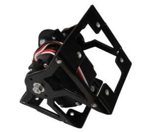
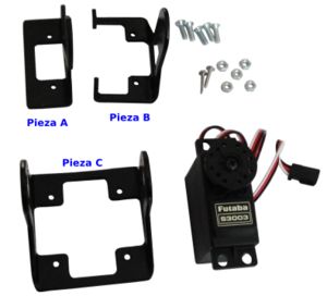
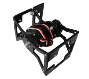
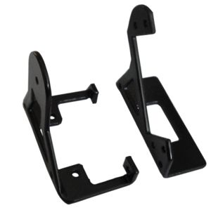
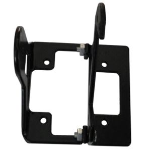
The MY1 modules consist of three aluminium parts: A, B and C and a Futaba 3003 servo. In addition, five M3 8mm-in-length bolts and nuts are needed.
Assembling
Step 0: Remove the paint inside the drills (Optional)
The module parts are made of 2mm width aluminium. They have been painted in black. The inner part of the drills is also painted therefore its diameter is a little bit smaller. In order for the 3mm bolts to go smooth through the drills it is necessary to remove this paint using a rounded file.
Do it for all the holes in all the parts: A, B and C
Step 1: Join the A and B part
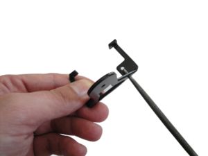
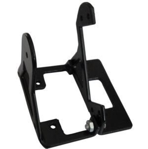
Parts A and B are joined by means of M3 bolts and nuts. They form the body of the module, where the servo will be screwed.
- a) Find the A and B pieces. Place the parts as shown in figure a.
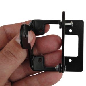
- b) Insert the first bolt with a nut
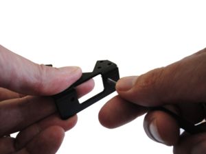
- c) Align the drills corresponding to parts A and B. Sometimes it is necessary to force a little bit the part B.
- d) Insert the bolt and nut.
Pictures
| Photo album |
Links
News
- 19/Feb/2011: This page is started
